Free Printable Classroom Posters PDF: Comprehensive Library Overview
Explore a free library of 28+ printable classroom posters in PDF, featuring science visuals, grammar guides, and motivational quotes. Download instantly, use for lessons, presentations, or wall displays, and keep learning vibrant accessible. Students love designs; educators customize freely.
Top Free Sources: Clipart, SignUp.com, Education.com, Teachers Pay Teachers
Clipart offers a curated set of 28 high‑quality, curriculum‑aligned posters that can be downloaded as PDFs. Each file contains vibrant illustrations of alphabets, numbers, shapes, and science diagrams, ready for instant printing. SignUp.com hosts a collection of 27 themed poster sets, ranging from inspirational quotes to classroom management charts, all free to download and printable in PDF format. Education.com provides a broader library of printable resources, including grammar guides and science visuals, with a simple search function that filters by grade level and subject. Teachers Pay Teachers, while primarily a marketplace, also features a selection of free poster packs; educators can sign up for a free account to access these resources without cost. All these platforms offer direct PDF downloads, ZIP archives, and browser‑save options, ensuring compatibility across operating systems. The PDFs are designed to be print‑ready, with high resolution and bleed‑free margins, making them suitable for both home and classroom use. Users can customize the posters using free PDF editors such as PDFescape or Inkscape, adding personalized messages or classroom rules. The combination of free access, diverse subject coverage, and easy customization makes these sources ideal for teachers seeking to enhance visual learning environments without incurring additional expenses.

Subject‑Specific Collections: Science Visuals, Grammar Guides, Motivational Quotes
Free printable classroom posters in PDF are organized into clear subject‑specific collections that cater to diverse teaching needs. The science visuals set features high‑resolution diagrams of the solar system, the water cycle, and cell biology, each labeled with concise captions for quick reference. These posters are ideal for science labs, classroom walls, or handouts, and can be printed in full color on standard 8.5×11 paper. The grammar guides collection covers parts of speech, punctuation rules, and sentence structure, presented in a colorful, child‑friendly layout. Each guide includes examples, practice prompts, and visual cues that reinforce learning objectives for grades K‑6. Motivational quotes are grouped into themed sets—“Believe in Yourself,” “Growth Mindset,” and “Kindness Matters”—and feature bold typography and uplifting imagery. These posters can be hung in reading corners, transition areas, or as part of a daily routine to foster a positive classroom culture. All PDFs are downloadable directly from the source sites, with options to save or print immediately. Teachers can further customize the posters by adding their own messages or class rules using free PDF editors, ensuring the resources fit their unique classroom context. The subject‑specific approach allows educators to quickly locate the exact visual aid they need, streamlining lesson planning and enhancing student engagement. Teachers report increased student participation when these visuals are displayed prominently, citing improved recall and a more inviting learning environment.
In addition, many of these collections include supplementary worksheets that align with the posters, offering interactive activities such as matching, fill‑in‑the‑blank, or labeling exercises. The worksheets are also available in PDF format, ensuring consistency across all materials. By integrating the posters with these activities, teachers create a cohesive learning experience that reinforces concepts through visual and kinesthetic engagement. The free nature of these resources means that schools with limited budgets can still provide high‑quality visual aids without compromising on design or educational value. Because the PDFs are vector‑based, they can be scaled to larger sizes—such as poster boards or bulletin boards—without loss of clarity, making them versatile for both small desks and large classroom walls. This flexibility, combined with the ease of download and customization, makes the subject‑specific collections a cornerstone for modern, student‑centered instruction.
Download Formats: PDF, ZIP, Direct Links and Browser Saving Tips
When accessing free printable classroom posters, most providers offer the content in several convenient formats. The primary format is a single PDF file, which retains vector graphics and layout fidelity across devices. For educators who wish to download a whole collection at once, a ZIP archive is often available; this bundle contains individual PDFs, high‑resolution PNGs, and sometimes editable source files such as InDesign or Illustrator documents. Direct download links bypass the need for a login, allowing instant access from the source page. To save a PDF directly from the browser, right‑click the link and select “Save link as…” or use the browser’s download bar to confirm the file name and destination. For mobile users, tapping the link will prompt the device to open the PDF in a viewer, where the “Share” or “Export” option can be used to move the file to a cloud folder or print queue. Some sites provide a “Download All” button that triggers a ZIP download; after extraction, the PDFs are ready for printing or editing. It is advisable to check the file size before downloading large ZIPs, as high‑resolution images can increase the archive size. When saving PDFs, choose a folder that is easy to locate, such as a dedicated “Classroom Resources” directory. Finally, remember that most browsers allow you to set a default download location, which can streamline future resource acquisition. By understanding these formats and saving techniques, teachers can efficiently gather and organize visual aids for classroom use.

Design & Customization Techniques for Classroom Posters
Use free PDFs to add text, colors, or images. Edit with PDFescape or Inkscape, resize, and print on cardstock. Collage cut‑paper or digital layers create engaging, personalized visuals for any grade level. Perfect for quick classroom updates. Customize fonts and backgrounds for a unique look. Enjoy!
Collage Methods Using Cut Paper and Digital Tools
Free printable classroom posters PDFs can be transformed into vibrant collages by cutting paper shapes, letters, and images. Teachers cut out alphabet blocks, numbers, or science icons from colored cardstock and arrange them on a poster sheet; This tactile method reinforces visual learning and keeps students engaged.

Digital tools complement the physical approach. Programs like Canva, GIMP, or Inkscape allow educators to layer PDF graphics, add text, and insert clipart. By importing the PDF into the software, users can resize elements, change colors, or overlay transparent images to create a polished, cohesive design. Export the final artwork back to PDF for high‑resolution printing.
Combining cut‑paper collages with digital edits yields a dynamic classroom display. The physical cutouts add texture, while the digital layers provide consistency and easy updates. This hybrid technique supports diverse learning styles and keeps walls fresh without extensive redesign.
When students create their own collages, they practice fine motor skills and critical thinking. Teachers can provide templates, color palettes, and prompts to guide the process. The resulting posters become a collaborative showcase, reflecting classroom culture and reinforcing the curriculum in a visual, memorable way.
Teachers can print the final PDFs on matte or glossy stock, laminate, and rotate displays to keep environment fresh!! .

Colorful Layouts to Engage Students and Enhance Visibility
Bright, bold, and strategically arranged, colorful layouts turn ordinary classroom walls into dynamic learning hubs. By layering high‑contrast hues—such as teal with coral, mustard with navy, or magenta with lime—teachers create visual anchors that capture attention and aid memory retention. The key is to balance saturation with readability: use lighter backgrounds for text blocks and darker accents for headings, ensuring that essential information stands out without overwhelming the eye. Incorporating graphic elements like arrows, icons, and borders not only guides the viewer’s gaze but also reinforces concepts; for instance, a science poster might feature a stylized atom surrounded by orbiting planets, while a grammar guide could display a sentence with highlighted parts of speech in distinct colors.
When designing PDFs, consider the viewing distance. Elements larger than 2‑inch for text and 3‑inch for images remain legible from the back of the room. Employing a grid system keeps alignment consistent, while a subtle drop shadow or outline around text enhances contrast against busy backgrounds. For interactive posters, embed QR codes or hyperlinks that link to supplementary videos or quizzes, allowing students to engage beyond the printed surface. Additionally, rotating color schemes seasonally—such as pastel palettes in spring or jewel tones in winter—keeps the environment fresh and encourages students to revisit familiar content with renewed interest.
Finally, involve students in the design process. Provide templates and color‑matching worksheets, letting them choose hues that resonate with their learning styles. This collaborative approach not only boosts engagement but also fosters ownership of the learning space. By combining thoughtful color theory, strategic layout, and student participation, free printable classroom posters PDFs become powerful tools that elevate visibility, stimulate curiosity, and support academic success.
Editing PDFs with Free Tools (PDFescape, Inkscape) for Custom Messages
PDFescape and Inkscape provide powerful, zero‑cost options for tailoring classroom posters. With PDFescape, simply upload the downloaded PDF, select the “Text” tool, and type a new line. Adjust font, size, and color to match the poster’s theme, then lock background layers to avoid accidental edits. Save the file, and the original layout remains intact while your custom message appears prominently. Inkscape, a free vector editor, imports the PDF as editable layers. This lets you replace text blocks, modify shapes, or add new graphic elements such as arrows or icons. By choosing the “Text” tool, you can type a motivational quote or lesson title, then use the “Fill” and “Stroke” panels to align colors with the poster’s palette. Layers can be locked, ensuring background images stay unchanged while foreground text is updated. After editing, export back to PDF to preserve vector quality for high‑resolution printing. For quick, on‑the‑fly changes, PDFescape’s browser interface is ideal; for complex redesigns that require precise vector manipulation, Inkscape offers greater flexibility. Always keep a backup of the original PDF before making alterations, and test the final file on a small print to confirm that fonts and colors appear as intended on the classroom wall. This workflow empowers teachers to add personalized messages, update lesson content, or create themed posters for special events—all without purchasing new graphics.
When adding custom messages, choose fonts that balance readability and style. Sans‑serif fonts like Arial or Helvetica work well for large headings, while a playful script can emphasize key points. In Inkscape, the “Text to Path” feature lets you curve text around shapes, creating eye‑catching designs. If you need to embed images, use the “Place Image” function to insert PNG or JPEG files directly into the PDF, then adjust opacity to blend with the background. Both tools support exporting to PDF/A format, ensuring long‑term archival compatibility. Share the edited poster with colleagues via Google Drive or a classroom LMS, and invite collaborative feedback to refine the design further. By leveraging these free tools, educators transform static printable posters into dynamic, personalized learning aids that resonate with students and adapt to evolving curriculum needs.

Classroom Implementation Strategies
Place alphabet, number, shape, and grammar posters along hallway walls to reinforce daily learning. Add motivational quotes near the entrance to set a positive tone. Use safety signage in corners to remind students of rules, creating a structured, engaging environment. Students thrive. Daily growth
Visual Literacy Aids: Alphabet, Numbers, Shapes, and Grammar Rules
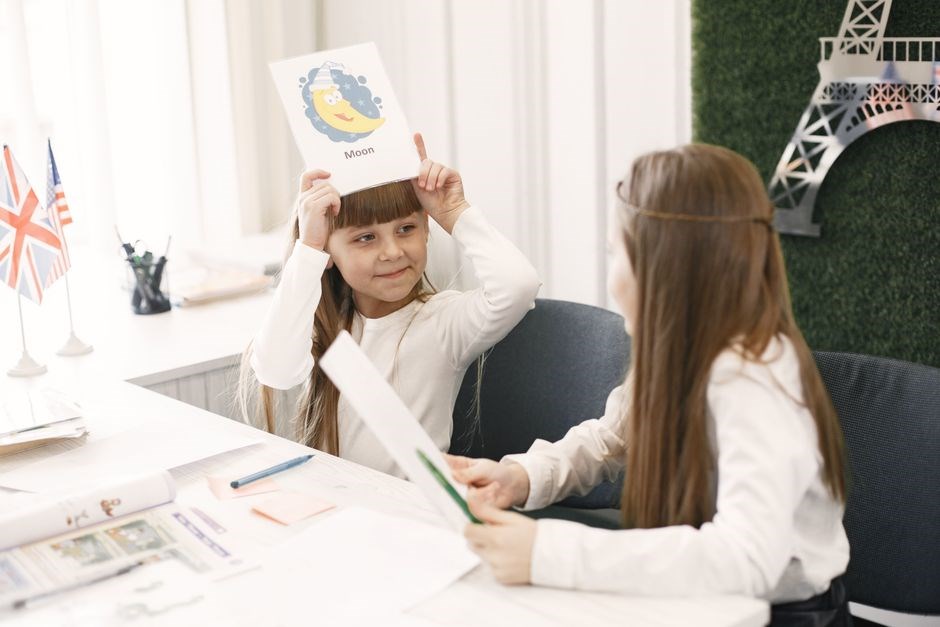
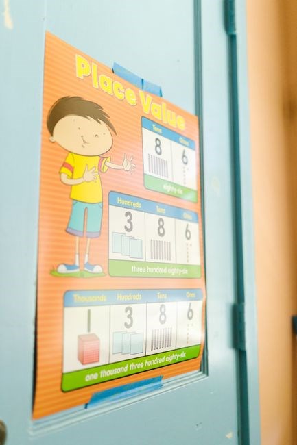
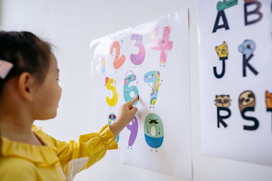
Free printable classroom posters in PDF format provide a versatile toolkit for reinforcing visual literacy. Alphabet posters feature large, bold letters paired with corresponding images, enabling students to associate phonics with concrete examples. Number posters display numerals from 0 to 100 alongside pictorial representations, supporting early numeracy and number sense; Shape posters highlight basic geometric figures—circles, squares, triangles—using bright colors and real‑world objects, fostering spatial awareness and vocabulary expansion. Grammar rule posters condense complex concepts into clear, concise visuals: subject‑verb agreement charts, punctuation usage diagrams, and sentence structure trees. Each poster is designed for high contrast and readability, ensuring that even students with visual processing challenges can engage. Teachers can strategically place these aids along classroom walls, near desks, or in high‑traffic areas to create a constant, passive learning environment. The PDFs are fully editable, allowing educators to customize text, colors, or add classroom‑specific examples without compromising print quality. By integrating these visual literacy aids into daily routines—such as morning review circles, math warm‑ups, or writing workshops—students receive repeated, multimodal exposure that reinforces retention and application. The combination of alphabet, number, shape, and grammar visuals supports differentiated instruction, enabling learners at varying proficiency levels to access content at their own pace. Additionally, the free nature of these resources reduces budget constraints, allowing schools to allocate funds toward interactive tools or additional learning materials. In sum, the free printable classroom posters PDF collection serves as an essential, adaptable resource for cultivating foundational literacy skills, promoting academic confidence, and enhancing classroom engagement across diverse learning environments.
Motivational & Inspirational Wall Messages for Positive Atmosphere
Free printable classroom posters in PDF format offer a rich selection of motivational and inspirational wall messages that help create a positive learning environment. These posters feature uplifting quotes, encouraging affirmations, and visually engaging designs that resonate with students of all ages. By placing them strategically around the classroom—near the entrance, in the reading corner, or on the main bulletin board—teachers can reinforce a growth mindset and celebrate achievements. Each poster is crafted with high‑contrast colors, bold typography, and simple graphics, ensuring readability from a distance. The PDFs are fully editable, allowing educators to personalize messages, add classroom names, or incorporate student‑created artwork without compromising print quality. The free nature of these resources means schools can rotate themes seasonally or align them with curriculum units, such as “Kindness Week” or “Science Innovation.” The inspirational content covers topics like perseverance, curiosity, teamwork, and resilience, providing daily reminders that learning is a collaborative, lifelong journey. Students can interact with the posters by writing their own goals or reflecting on progress, turning passive displays into active learning tools. Moreover, the printable format supports both digital and physical use: teachers can email PDFs to parents, share on class websites, or print in bulk for classroom walls. By integrating motivational wall messages into everyday routines—such as morning check‑ins, project showcases, or end‑of‑day reflections—educators foster a supportive atmosphere that encourages risk‑taking, self‑confidence, and a sense of belonging. Because the PDFs are vector‑based, they scale cleanly to any size, from small desk posters to large wall‑mounted displays, ensuring consistent quality across all formats. Teachers can also combine multiple motivational themes into a single poster set, creating a cohesive visual narrative that reinforces the school’s mission statement and core values.
Management & Safety Signage to Promote Classroom Order
Free printable classroom posters in PDF format provide essential management and safety signage that keeps the learning space organized and secure. These posters cover a wide range of topics—emergency exit routes, fire drill procedures, hand‑washing stations, classroom rules, and respectful behavior guidelines. Each design uses clear icons, concise wording, and high‑contrast colors so students can quickly read and remember the information. Because the PDFs are vector‑based, they print crisply at any size, from small desk signs to large wall‑mounted banners. Teachers can customize the text to match their specific classroom policies, add school logos, or insert student names, ensuring the signage feels personal and relevant. The free nature of these resources means educators can update or replace posters as needed without incurring additional costs. By placing safety signs near doors, windows, and the teacher’s desk, students develop a routine of checking for hazards and following procedures. Management posters such as “Quiet Time,” “Group Work,” or “Clean Up” help establish a predictable classroom rhythm, reducing disruptions and fostering a calm learning environment. The PDFs also include printable checklists for daily routines—attendance, materials distribution, or classroom maintenance—allowing teachers to track compliance and reinforce accountability. Because the files are downloadable, teachers can print multiple copies for different classrooms or share them with parents via email or the school’s learning management system. The combination of clear visuals, editable text, and cost‑effective distribution makes these management and safety posters a powerful tool for maintaining order, promoting safety, and supporting a positive classroom culture.!!!

Technical & Legal Aspects of Free Printable Posters
PDFs offer cross‑platform compatibility, editable layers, and print‑ready resolution. Use standard licensing info, provide attribution, and verify royalty‑free status. Follow school policy for redistribution and respect copyright terms
Benefits of PDF Format: Cross-Platform, Editable, Print-Ready
PDF files are the gold standard for classroom resources because they preserve layout, color, and typography across operating systems. Students and teachers can open a single file on Windows, macOS, Linux, or mobile devices without formatting loss. The embedded fonts and vector graphics ensure crisp, scalable images that remain sharp on high‑resolution printers. PDF’s native support for layers allows educators to toggle visibility of instructional elements, making it easy to create interactive worksheets or step‑by‑step guides. Editing tools such as PDFescape or Inkscape enable quick modifications—adding a new lesson title, updating a statistic, or inserting a student name—without the need to re‑design from scratch. Print‑ready PDFs include bleed marks and color profiles, guaranteeing that the final output matches the designer’s vision. Because the format is widely accepted by school IT departments, files can be shared via email, cloud storage, or learning management systems with minimal compatibility concerns. Overall, PDF offers a reliable, efficient, and versatile medium that supports dynamic teaching and ensures consistent visual quality. Teachers can also embed hyperlinks to online resources, making the posters interactive. The format’s compression keeps file sizes small, enabling quick downloads even on limited bandwidth. Additionally, PDFs can be password‑protected or watermarked to safeguard intellectual property. When printed on matte cardstock, the colors appear vibrant, and the paper thickness resists tearing during daily use.
Printing Guidelines: Paper Choice, Color Profiles, Print Settings
When printing free classroom posters, choose a matte or semi‑gloss cardstock (80–120 lb) to reduce glare and give a professional feel. Heavier stock (120–150 lb) resists tearing for larger posters. Recycled matte cardstock is eco‑friendly and opaque. Convert PDFs to the printer’s native color profile—most school printers use sRGB; Adobe RGB can be used if the printer supports it, but embed the profile. In the print dialog, select “High Quality” or “Best,” set resolution to 300 dpi, and enable “Print on Both Sides” for double‑sided posters. Disable automatic scaling unless the poster is designed to fill the sheet; otherwise margins shift important text. Use the “Color Management” tab to choose the correct printer profile, often downloadable from the manufacturer’s website. Preview the job to ensure bleed marks and crop lines are preserved. For very large posters, use a professional printing service that offers full‑bleed options and handles custom dimensions. If your school shares a printer, request a test print on a single sheet to verify fonts and images are crisp before committing to a full set. Calibrate the printer with a hardware calibration device or a color wheel to guarantee printed colors match the on‑screen design. Keep a backup of the original PDF in a cloud folder so future edits or re‑prints can be made without loss of quality. Print on a high‑resolution inkjet or laser printer to ensure crisp lines and vibrant colors. Use a paper cutter or guillotine for clean edges. Label each poster with a unique identifier for inventory tracking. Store printed posters in a dry, cool place to prevent fading. If color accuracy is critical, perform a color check with a swatch card. For large volumes, consider bulk printing discounts; Keep a digital copy of the PDF for future updates. Encourage students to help with hanging to foster ownership.
Licensing & Attribution Requirements to Ensure Legal Use
Free printable classroom posters often come with Creative Commons or public‑domain licenses. Before printing, read the license details on the download page. For CC‑BY, you must credit the creator, include the title, and link back to the source. CC‑BY‑SA requires you to share any derivative work under the same license. CC‑0 releases the poster into the public domain, so no attribution is needed, but it is courteous to acknowledge the author. Some sites add a “No Commercial Use” clause; if you plan to display posters in a school that receives funding or sells materials, verify that the license permits such use. When you modify a poster—adding text, changing colors, or combining images—ensure that the new work remains compliant; if the original license is CC‑BY, attribution must still be provided. For non‑CC licenses, check the terms of use; many free resources allow non‑commercial educational use but forbid redistribution. If you redistribute the poster, either keep the original file or provide a link to the source. Always keep a record of the license version and download date. If you are unsure, contact the author or the platform’s support. Some platforms automatically embed a license statement in the PDF; include that statement in any printed version. Finally, respect the spirit of the license: avoid altering the poster in ways that misrepresent the creator or the content. By following these guidelines, you maintain legal use and support the creators who share their work for free. Remember to archive the PDF with its license metadata for future reference.